
Ultrasonic Welding Plastic: Joint Design and Materials
Ultrasonic welding plastic parts joins them with high-frequency vibration instead of screws, adhesives or clips. The vibration creates friction heat at the joint, the plastic melts locally and solidifies under pressure in less than a second. It is fast, clean and repeatable, which makes it popular for housings, filters, medical parts and electronics enclosures.
Most weld problems start in the molded part, not in the welder. For example, a housing with no energy director may weld unevenly and leak. A part whose joint height varies by a few tenths of a millimeter may weld strongly on one side and weakly on the other. In this guide, we explain how to design molded parts for ultrasonic welding plastic: material choice, joint design, energy directors, dimensional variation, fixtures and weld testing. For other assembly options, see our guide to molded threads.
Ultrasonic welding plastic uses vibration at about 15–40 kHz, applied through a horn under pressure, to melt the joint interface in roughly 0.1–1 second. It works best on amorphous plastics such as ABS, PC and PMMA; semi-crystalline plastics such as PP, PA and POM need more energy and shear joints. Molded parts need a defined joint, usually a triangular energy director about 0.25–0.6 mm high or a shear joint, consistent wall and joint dimensions, a near-field weld zone and support in a fixture. Weld quality is checked by burst, leak or pull tests.
In short: choose a weldable material, design a proper joint with an energy director or shear joint, and control joint dimensions in molding.
Key points:
- Materials: amorphous plastics weld most easily.
- Joint: energy directors focus the energy.
- Variation: joint dimensions must be tightly controlled.
How Does Ultrasonic Welding Plastic Work?
Ultrasonic welding plastic works by converting electrical energy into mechanical vibration, which a horn transmits to the parts.
The cycle:
- Load parts into the fixture (nest).
- Horn contacts the top part and applies force.
- Vibration melts the joint interface.
- Hold: vibration stops, and pressure holds while the melt solidifies.
- Release: the welded assembly is removed.
Welding can be controlled by time, energy or collapse distance. For example, welding to a fixed collapse distance gives a consistent final height, even if parts vary slightly. Our secondary processing page lists assembly and post-molding operations.
Key Takeaway: Weld by distance when final height matters. It compensates for small part variation.
Which Materials Work for Ultrasonic Welding Plastic?
Materials for ultrasonic welding plastic work best when they transmit vibration well and melt over a narrow range.
| Material type (typical) | Weldability | Joint type |
|---|---|---|
| Amorphous (ABS, PC, PMMA, PS) | Excellent | Energy director |
| Semi-crystalline (PP, PA, POM, PBT) | Good with care | Shear joint preferred |
| Filled grades (up to about 30% glass) | Usually good | Depends on grade |
| Soft materials (TPE, flexible PVC) | Poor | Other methods |
| Dissimilar materials | Limited | Only compatible pairs |
For example, two ABS halves weld easily with an energy director, while two PP halves usually need a shear joint for a strong, sealed weld. In addition, moisture in nylon can cause foamy welds, so nylon parts should be welded dry. Our guide to nylon 6 vs nylon 66 explains nylon moisture behavior.
Key Takeaway: Confirm material compatibility before designing the joint. Some pairs will not weld.
How Do You Design an Energy Director for Ultrasonic Welding Plastic?
You design an energy director for ultrasonic welding plastic as a small triangular ridge on one joint face, which concentrates energy and melts first.
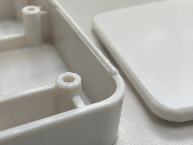
Energy director guidelines:
- Shape: triangle with a 60° or 90° included angle
- Height: about 0.25–0.6 mm, depending on part size and material
- Base width: about twice the height for 90° designs
- Location: centered on the mating wall
- Continuity: unbroken around the joint for sealed welds
For example, a 0.5 mm high energy director on a 2 mm wall gives enough melt to fill the joint and form a hermetic seal. A director that is too small leaves a weak weld, while one that is too large creates flash. Adding a flash trap, a small groove beside the joint, hides excess melt on cosmetic parts.
Key Takeaway: Put the energy director on the part with the easier mold access, and add flash traps on visible parts.
When Should You Use a Shear Joint Instead?
You should use a shear joint instead of an energy director for semi-crystalline plastics and for strong, hermetic seals.
Shear joint features:
- Interference: a small overlap, often about 0.2–0.4 mm per side
- Depth: the weld depth, typically about 1.25–1.5 times the wall thickness
- Lead-in: a step that aligns the parts before welding
- Support: the outer wall must be supported by the fixture
For example, a PP filter housing that must pass a pressure test usually uses a shear joint, because the melt forms along the vertical walls and resists peeling. Our guide to polypropylene vs polyethylene covers PP properties.
Key Takeaway: For PP, PA and POM, start with a shear joint. Energy directors often give weak welds in these materials.
How Does Dimensional Variation Affect Ultrasonic Welding Plastic Parts?
Dimensional variation affects ultrasonic welding plastic parts because the joint must meet evenly around its full length. Uneven contact means uneven melting.
Common variation sources:
- Warpage of the joint face
- Height variation of the energy director
- Cavity-to-cavity differences in multi-cavity molds
- Shrinkage differences between material lots
- Sink marks at the joint
Controls in molding:
- Tolerances on joint dimensions, tighter than on non-functional features
- Flatness requirement on the joint face
- Per-cavity measurement of joint height
- Uniform walls to reduce warpage
For example, a housing that warps 0.3 mm along its long side may weld well at the corners but leave a gap in the middle. Our guide to injection molding tolerances explains realistic limits.
Key Takeaway: Treat the weld joint as a critical feature on the drawing, with flatness and height tolerances.
How Should Welded Parts Be Tested?
Welded parts should be tested with methods that match their function, both at setup and during production.

Common tests:
- Burst or pressure test for sealed housings
- Leak test with air or helium
- Pull or peel test for mechanical strength
- Cross-section to check melt and voids
- Visual check for flash, marks and cracks
For example, a filter housing may be pressure tested on every part, while a toy housing may only need a sampled pull test. Plastics welding terms and test approaches are covered in standards from bodies such as ISO.
Key Takeaway: Define weld acceptance tests with the molded part design, not after the first failures.
FAQ
- Q: What plastics can be ultrasonically welded?
- Most thermoplastics, especially amorphous ones like ABS, PC and PMMA. Semi-crystalline plastics need more energy and shear joints.
- Q: What is an energy director?
- A small triangular ridge on one joint face that concentrates ultrasonic energy and melts first.
- Q: How high should an energy director be?
- Typically about 0.25–0.6 mm, depending on part size and material.
- Q: Can PP be ultrasonically welded?
- Yes, but a shear joint usually works better than an energy director.
- Q: Why do ultrasonic welds leak?
- Often because of uneven joint height, warpage, a broken energy director or wrong weld settings.
Conclusion
Ultrasonic welding plastic parts works reliably when the material, joint and molded dimensions are designed for it. Choose the joint type by material, control joint flatness and height in molding, and define weld tests early. To review a welded assembly, send your 3D model and 2D drawing to our engineers.