
How to Do a Tolerance Stack Up Analysis: The Best Way to Save Time and Money
Knowing how to do a tolerance stack up analysis is essential when molded or machined parts must fit together. A stack-up adds the tolerances of every dimension in a chain, such as a housing wall, a PCB, a gasket and a cover, to check whether the critical gap or interference stays acceptable. Without it, parts that each meet their drawings can still fail to assemble, rattle or leak.
Molded assemblies make stack-ups especially important, because plastic dimensions vary with shrinkage, cavity, moisture and temperature. For example, a snap-fit cover may assemble perfectly with parts from cavity 1 but bind with parts from cavity 4. In this guide, we explain how to do a tolerance stack up analysis for molded assemblies: defining the CTQ, building the loop, worst-case and statistical (RSS) methods, molded-part factors, how to reduce the stack and how to connect results to drawings and inspection. For tolerance basics, see our guide to injection molding tolerances.
To do a tolerance stack up analysis, define the critical-to-quality (CTQ) gap or fit, draw the dimension loop from one side of the gap through each contributing part back to the other side, assign each dimension a nominal value and tolerance with a direction (+ or −), then add the nominals to get the nominal gap and combine tolerances by worst case (simple sum) or statistically (root sum of squares, RSS). Compare the result with the requirement. For molded parts, include shrinkage variation, cavity-to-cavity differences, moisture and thermal effects, and use the result to set drawing tolerances and inspection CTQs.
In short: define the gap, build the loop, sum nominals and combine tolerances by worst case or RSS, then act on the result.
Key points:
- CTQ first: one stack-up per critical gap or fit.
- Methods: worst case is safe; RSS is realistic for many parts.
- Molded factors: cavity, shrinkage, moisture and temperature.
What Is a Tolerance Stack-Up?
A tolerance stack-up is a calculation that shows how individual part tolerances combine to affect an assembly dimension.
Typical uses:
- Clearance gaps between moving or mating parts
- Interference fits for press fits and snaps
- Gasket compression in sealed housings
- Alignment of buttons, lenses and connectors
- Overall assembly length
For example, the gap between a button and its opening in a housing depends on the button size, the opening size and their positions. Our guide to snap fit design shows a common stack-up case.
Key Takeaway: Every critical gap or fit deserves its own stack-up.
How to Do a Tolerance Stack Up Analysis Step by Step
Here is how to do a tolerance stack up analysis step by step.

- Define the CTQ: the gap or fit and its limits, for example gap 0.2–0.8 mm.
- Choose a direction: decide which way is positive.
- Build the loop: trace dimensions from one side of the gap through each part back to the other side.
- List each dimension with nominal, tolerance and sign.
- Sum the nominals to get the nominal gap.
- Combine tolerances by worst case and, if appropriate, RSS.
- Compare the result with the CTQ limits.
- Act: change design, tolerances or process if it fails.
For example, a loop of four dimensions with ±0.1 mm each gives ±0.4 mm worst case and about ±0.2 mm RSS.
Key Takeaway: Draw the loop on paper or CAD first. Most stack-up errors are missing dimensions.
What Is the Difference Between Worst-Case and RSS Stack-Ups?
The difference between worst-case and RSS stack-ups is how they combine tolerances.
| Method | Calculation | Assumption | When to use |
|---|---|---|---|
| Worst case | Sum of all tolerances | All parts at extremes together | Safety-critical, low volume, few dimensions |
| RSS (statistical) | √(sum of tolerance²) | Variations are random and centered | Volume production, many dimensions |
| Modified RSS | RSS × factor (e.g. 1.5) | Allows for non-ideal processes | Common practical compromise |
For example, worst case guarantees fit but often forces very tight tolerances. RSS allows wider part tolerances but accepts a small risk. Statistical tolerancing concepts are described in standards from ISO.
Key Takeaway: Use worst case when failure is unacceptable; use RSS when processes are capable and centered.
How to Do a Tolerance Stack Up Analysis for Molded Parts
When you learn how to do a tolerance stack up analysis for molded parts, remember that their dimensions vary in ways that machined parts usually do not.
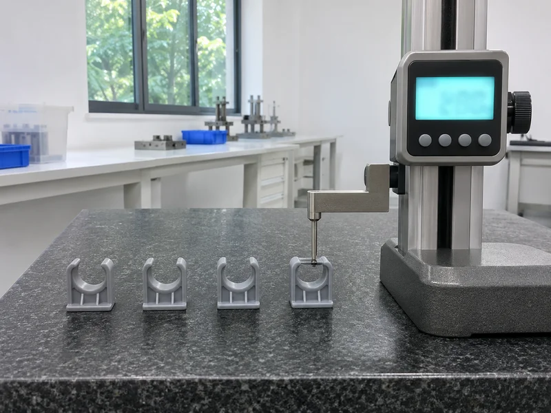
Molded-part factors:
- Shrinkage variation with process and material lot
- Cavity-to-cavity differences in multi-cavity molds
- Moisture absorption, especially in nylon
- Thermal expansion, higher than metals
- Warpage affecting flatness and position
- Mold wear over time
For example, a PA66 part may grow 0.3–0.5% after absorbing moisture. A stack-up done with dry dimensions may fail in service. Our guide to plastic shrinkage explains shrinkage variation.
Key Takeaway: Include cavity, moisture and temperature in molded stack-ups.
How Do You Reduce a Tolerance Stack-Up?
You reduce a tolerance stack-up by shortening the loop, tightening the right dimensions and using locating features.
Methods:
- Fewer parts in the loop: combine parts or reference directly.
- Datum-based design: locate parts on functional features.
- Tighten only the biggest contributors.
- Use adjustable or compliant features, such as crush ribs or slots.
- Single-cavity or matched-cavity assemblies for critical fits.
- Steel-safe tuning of the mold after trial.
For example, locating a cover on two pins molded into the housing removes the housing’s outer profile from the loop. Our guide to GD&T position tolerance explains locating features.
Key Takeaway: Shorten the loop before tightening tolerances.
How Do Stack-Up Results Connect to Drawings and Inspection?
Stack-up results connect to drawings and inspection by defining which dimensions and tolerances matter most.
Links:
- Drawing tolerances set from the stack-up allocation
- CTQ marks on contributing dimensions
- Inspection plans that measure CTQs per cavity
- Capability targets (for example Cpk) for RSS assumptions
- Assembly checks on first articles
For example, if the stack-up assumed RSS, the CTQ dimensions should be monitored for capability, because RSS only holds when processes are centered. Our guide to the control plan explains how CTQs are monitored.
Key Takeaway: An RSS stack-up needs capability data to stay valid.
How to Do a Tolerance Stack Up Analysis With the Right Tools
The right tools range from spreadsheets to 3D simulation.
- Spreadsheets: simple 1D loops, quick and transparent
- CAD-based tools: extract dimensions from the model
- 3D tolerance simulation: Monte Carlo analysis for complex assemblies
- Mold flow results: predict shrinkage and warpage contributions
For example, a 1D spreadsheet is enough for a cover gap, while a multi-part assembly with angles may need 3D simulation. Our engineering and DFM review checks critical fits during design.
Key Takeaway: Start simple. Use 3D tools when loops include angles or many parts.
FAQ
- Q: How do you do a tolerance stack-up analysis?
- Define the CTQ, build the dimension loop, sum nominals and combine tolerances by worst case or RSS.
- Q: What is the difference between worst case and RSS?
- Worst case adds all tolerances; RSS takes the square root of the sum of squares.
- Q: When should RSS be used?
- For volume production with capable, centered processes and several dimensions.
- Q: What makes molded-part stack-ups different?
- Shrinkage, cavity differences, moisture and thermal expansion.
- Q: How can a failing stack-up be fixed?
- Shorten the loop, use locating features and tighten the largest contributors.
Conclusion
Learning how to do a tolerance stack up analysis prevents fit problems in molded assemblies. Define the CTQ, build the loop, choose worst case or RSS, include molded-part effects and connect the results to drawings and inspection. To review an assembly, send your 3D model and 2D drawing to our engineers.