
Snap Fit Design: Strain Calculation and Design Rules
Snap fit design lets molded parts click together without screws, adhesives or welding. A well-designed snap fit assembles quickly, holds reliably and, if required, can be released for service. A poor one cracks at the root, loosens after a few cycles or needs so much force that assembly workers complain. The difference is mostly in strain, geometry and material choice.
Snap fits fail most often because the designer sized the hook for appearance or space rather than for allowable strain. For example, a short, thick cantilever on a glass-filled nylon cover may crack on first assembly, while a longer, tapered beam of the same material would flex safely. In this guide, we explain snap fit design for molded assemblies: joint types, cantilever calculation, allowable strain by material, design rules, tooling, press fits as an alternative and how to validate fit. For other joining methods, see our guide to ultrasonic welding plastic.
Snap fit design starts with choosing a joint type (cantilever, annular or torsional), then sizing the beam so that the strain during assembly stays below the material’s allowable limit, typically about 1–2% for glass-filled resins and 4–8% for unfilled tough resins such as PC, ABS or PP. For a rectangular cantilever, strain ≈ 1.5 × thickness × deflection ÷ length². Tapered beams, root radii, suitable lead-in and retention angles and undercut-friendly tooling make snap fits reliable. Validate with assembly force, retention force and cycle tests on molded parts.
In short: pick the joint type, keep strain within the material limit, add root radii and test on real parts.
Key points:
- Strain rules: allowable strain decides beam size.
- Geometry: length, taper and root radius prevent cracking.
- Tooling: undercuts need lifters, slides or bypass openings.
What Is Snap Fit Design?
Snap fit design is the engineering of flexible features that deflect during assembly and spring back to lock parts together.
Main joint types:
- Cantilever snap fits: a beam with a hook; the most common type.
- Annular snap fits: a ring around a cylinder, such as caps.
- Torsional snap fits: a lever that twists around a shaft.
For example, a battery cover often uses cantilever hooks, while a bottle cap uses an annular snap. Our guide to 8 ways to achieve undercut success covers how undercuts are molded.
Key Takeaway: Choose the joint type by assembly direction, load and whether it must release.
How Do You Calculate Strain in Snap Fit Design?
You calculate strain in snap fit design from the beam’s thickness, length and the deflection needed to pass the hook.
For a uniform rectangular cantilever:
- Strain ε ≈ 1.5 × t × y ÷ L²
- t = beam thickness at the root
- y = deflection (hook depth)
- L = beam length
For example, a beam 1.5 mm thick and 15 mm long deflecting 1.2 mm gives ε ≈ 1.5 × 1.5 × 1.2 ÷ 225 ≈ 1.2%. That is fine for PC but close to the limit for a glass-filled grade. A beam tapered to half thickness at the tip lowers root strain further. Material design data are published by resin suppliers and test standards from ASTM International.
Key Takeaway: Lengthen or taper the beam before making it thicker. Thickness raises strain.
What Allowable Strain Should You Use for Each Material?
The allowable strain depends on material and whether the snap is assembled once or many times.
| Material (typical) | Allowable strain, single assembly | Repeated assembly |
|---|---|---|
| PC | about 4% | about 2% |
| ABS | about 2.5–3% | about 1.5% |
| PC/ABS | about 3% | about 1.5% |
| PP | about 6–8% | about 4% |
| POM | about 6% | about 3% |
| PA6 (conditioned) | about 6% | about 3% |
| PA66-GF30 | about 1.5–2% | about 1% |
| PBT-GF30 | about 1.5% | about 0.8% |
Values vary by grade and temperature, so confirm with supplier data. Our guide to glass filled nylon explains why filled grades are less forgiving.
Key Takeaway: Use the repeated-assembly limit for snaps that will be opened in service.
What Are the Key Design Rules for Snap Fit Design?
The key rules for snap fit design control stress at the root, assembly force and retention.
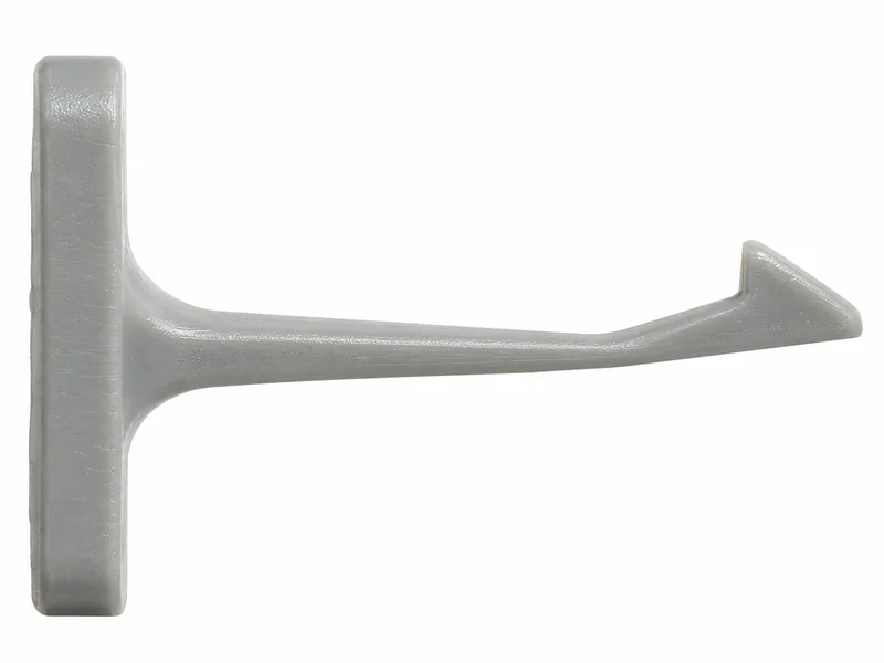
Design rules:
- Root radius: at least 0.5 × beam thickness to reduce stress concentration
- Beam taper: reduce thickness toward the tip
- Lead-in angle: about 25–35° for easy assembly
- Retention angle: about 90° for permanent joints, 35–45° for releasable joints
- Beam length: at least 5 × thickness where space allows
- Avoid weld lines at the beam root
For example, adding a 0.5 mm root radius to a sharp-cornered hook can sharply reduce cracking. Our guide to the injection molding lifter explains how inward hooks are released.
Key Takeaway: A root radius is the cheapest snap fit improvement.
How Are Snap Fits Molded?
Snap fits are molded with undercut-release methods built into the tool.
Common tooling options:
- Lifters for inward hooks
- Slides for outward or side hooks
- Bypass (pass-through) openings that form the hook without moving parts
- Stripping for small annular snaps in flexible materials
For example, a cover with internal hooks may use lifters, while designing the hooks with a window in the wall below lets the core form them with no moving parts. The second option lowers tool cost. Our guide to side action injection molding explains slide design.
Key Takeaway: Discuss hook geometry with the toolmaker early. A bypass opening can save a lifter.
When Is Plastic Press Fit Design Better Than a Snap Fit?
Plastic press fit design is better than a snap fit when parts need a permanent, tight joint without hooks, such as bushings, pins or bearings in bosses.
Press fit guidance:
- Interference calculated from hoop stress and allowable strain
- Boss wall thickness sufficient to resist cracking
- Creep reduces holding force over time, especially at temperature
- Lead-in chamfers for assembly
- Ribs (crush ribs) to tolerate variation
For example, a metal pin pressed into a PC boss may crack the boss if interference is too large; crush ribs give more tolerance. Our guide to the screw boss explains boss design.
Key Takeaway: Use snap fits for clip-together parts and press fits for pins and bushings.
How Do You Validate Snap Fit Design?
You validate snap fit design by testing molded parts, not only CAD models.

Validation tests:
- Assembly force measured on a force tester
- Retention force or pull-out force
- Cycle test for releasable snaps
- Temperature tests at high and low limits
- Conditioning of nylon parts before testing
- Visual check for stress whitening at the root
For example, a snap that assembles at 30 N at room temperature may need 50 N at −20 °C. Testing at both covers real use. Our plastic injection molding service supports sample runs for such tests.
Key Takeaway: Test snaps at temperature extremes and after conditioning.
FAQ
- Q: What is a snap fit?
- A flexible molded feature that deflects during assembly and springs back to lock parts together.
- Q: How do you calculate snap fit strain?
- For a uniform cantilever, strain ≈ 1.5 × thickness × deflection ÷ length².
- Q: What is the best material for snap fits?
- Tough, ductile materials such as PP, POM, PC and nylon; filled grades allow less strain.
- Q: Why do snap fits crack?
- Usually excessive strain, sharp root corners or weld lines at the root.
- Q: How are snap fit undercuts molded?
- With lifters, slides or bypass openings in the part wall.
Conclusion
Snap fit design succeeds when strain stays within the material limit, the root has a radius and the tooling can release the hook simply. Validate on molded parts at real temperatures. To review a snap fit assembly, send your 3D model and 2D drawing to our engineers.