
Screw Boss Design: Dimensions, Ribs and Stress Whitening
A screw boss is a cylindrical post on a molded part that receives a screw, often a self-tapping screw or a threaded insert. It is one of the most common features on plastic housings, and one of the most common sources of failure. A badly designed screw boss can crack at its root, turn white with stress, sink on the cosmetic face or slowly lose clamp force as the plastic creeps.
Fortunately, these failures are predictable and avoidable. For example, a boss with an outer diameter too small for the screw may split during assembly, while a boss that is too thick causes a sink mark on the visible side. In this guide, we explain screw boss design for injection molded parts: dimensions, ribs, draft and radii, stress whitening, root cracking, creep under preload and screw or insert choice. For general design rules, see our guide to basics of injection molding design.
A screw boss for self-tapping screws typically has a hole diameter of about 0.75–0.85 × the screw’s major diameter (depending on the resin), an outer diameter of about 2–2.5 × the screw diameter, a wall thickness of about 50–70% of the nominal wall at the base to avoid sink, a root radius of about 0.25–0.5 mm, gussets to support tall bosses, and a counterbore or lead-in at the top. Engagement length is typically about 2–2.5 × the screw diameter. Stress whitening and cracking come from excessive hoop stress or sharp roots; creep under preload is reduced by lower torque, larger contact areas, metal inserts or stiffer resins.
In short: size the hole and outer diameter for the screw and resin, support the boss with gussets, add root radii and plan for creep.
Key points:
- Dimensions: hole about 0.75–0.85 × screw OD; boss OD about 2–2.5 ×.
- Root: radius and controlled wall thickness to avoid cracks and sink.
- Creep: use inserts or design for long-term clamp loss.
What Is a Screw Boss?
In simple terms, a screw boss is a molded post that provides material for a screw to engage. It lets two parts be fastened without separate nuts.
Common screw boss types:
- Thread-forming screw bosses, where the screw deforms the plastic
- Bosses for thread-cutting screws, used in harder or brittle plastics
- Insert bosses, with inserts pressed, heat-staked or molded in
- Clearance bosses, through which a screw passes
For example, a PC/ABS electronics housing often uses thread-forming screws into bosses on the base, with clearance bosses on the lid. Our guide to insert molding design guidelines covers molded-in inserts.
Key Takeaway: Decide the fastener type first. It sets the boss geometry.
What Are the Basic Screw Boss Dimensions?
In general, the basic screw boss dimensions follow the screw size and resin, with recommendations from screw makers for each plastic.
| Feature (typical) | Guideline |
|---|---|
| Pilot hole diameter | ≈0.75–0.85 × screw major diameter |
| Boss outer diameter | ≈2–2.5 × screw major diameter |
| Engagement length | ≈2–2.5 × screw major diameter |
| Boss wall at base | ≈50–70% of nominal wall |
| Draft on outside | ≈0.5–1° |
| Lead-in or counterbore | ≈0.5 × screw diameter deep |
For example, for an M3 thread-forming screw in ABS, a pilot hole of about 2.4–2.5 mm and an outer diameter of about 6–7 mm is a common start. Always confirm with the screw maker’s data for the exact resin. Screw thread standards come from bodies such as ISO.
Key Takeaway: Start from the screw maker’s recommendation for your resin, then validate with assembly tests.
How Does Boss Design Change With the Fastener?
Boss design changes with the fastener, because a self-tapping screw, a heat-set insert and a molded-in insert load the boss in different ways.
| Fastener | Typical boss design | Main risk |
|---|---|---|
| Thread-forming screw | OD ≈2–2.5 × screw diameter, hole per screw maker data | Hoop stress and cracking |
| Heat-set or ultrasonic insert | Hole sized to insert data, wall ≥1.5 mm around the insert | Melt flow into threads |
| Molded-in insert | Insert held on a mold pin, boss wall around knurl | Stress at the insert and weld lines |
| Locating boss (no screw) | Thin wall, generous draft, cored | Sink on the cosmetic side |
For example, a boss that holds a brass insert in a housing that is opened many times needs a thicker wall than a boss that takes one screw at assembly. Our guides to plastic threaded inserts and plastic housing design show these choices in context.
Key Takeaway: In other words, pick the fastener first, then size the boss for it.
How Do Ribs and Gussets Add Support?
Instead of extra thickness, ribs and gussets support a screw boss by stiffening it and spreading load into the wall, without making the boss thick.
Guidelines:
- Gussets: 2–4 around tall bosses, about 50–60% of the wall thickness
- Connecting ribs to nearby walls for stability
- Avoid thick junctions where ribs meet the boss
- Core out the boss base if it becomes thick
For example, a 15 mm tall boss without support may tilt or crack during screw driving. Three gussets keep it upright while keeping walls thin. Our guide to troubleshooting sink marks explains why thick bosses sink.
Key Takeaway: Support tall bosses with gussets instead of making them thicker.
Why Does a Screw Boss Show Stress Whitening?
Typically, a screw boss shows stress whitening when the plastic is strained beyond its elastic range, usually by hoop stress from the screw.
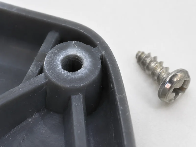
The most common causes are:
- Pilot hole too small for the screw and resin
- Boss outer diameter too small
- Over-torque during assembly
- Wrong screw type for the resin
- Brittle or low-elongation resin
For example, a white ring around the top of an ABS boss after assembly often means the pilot hole is undersized. Increasing it by 0.1–0.2 mm, or switching to a screw designed for plastics, removes the whitening. Our secondary processing covers assembly operations.
Key Takeaway: Whitening is an early warning. Fix the hole, boss size or torque before cracks appear.
How Do You Prevent Screw Boss Root Cracking?
Above all, you prevent screw boss root cracking by reducing stress concentration where the boss joins the wall.
To prevent it:
- Root radius: about 0.25–0.5 mm at the base
- Controlled wall thickness at the base to avoid voids and sink
- Avoid weld lines at the boss
- Gate location so the boss fills and packs well
- Proper drying for hygroscopic resins
For example, a PC boss with a sharp root and a weld line next to it may crack during assembly or later under load. Moving the weld line and adding a root radius usually solves it. Our guide to weld lines explains how to move them.
Key Takeaway: Check the boss root for sharp corners and weld lines. Both start cracks.
How Does Creep Affect a Screw Boss Under Preload?
Over time, creep affects a screw boss under preload because plastic slowly deforms under constant stress, so the screw loses clamp force over time.
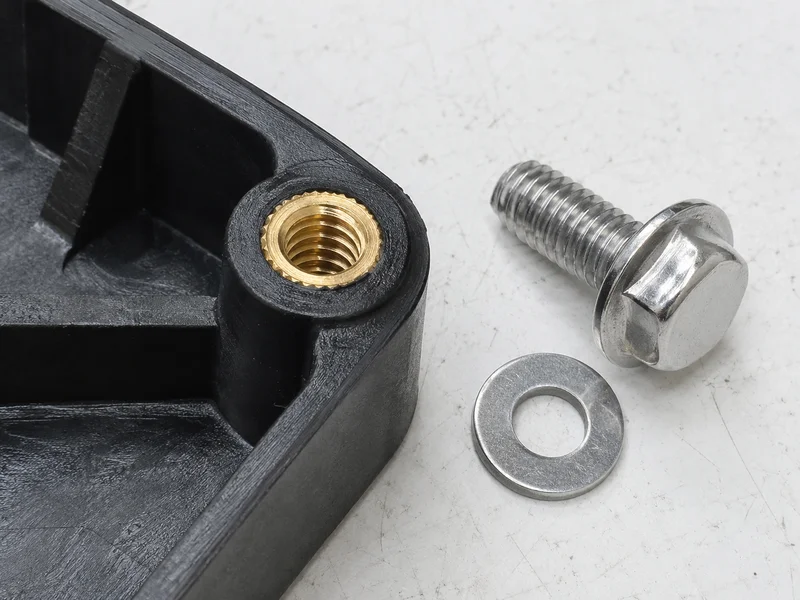
Factors that increase creep:
- Elevated temperature in service
- Excessive preload or over-torque
- Small contact area under the screw head
- Resin type: amorphous resins near their glass transition creep more
Ways to reduce creep effects:
- Metal threaded inserts
- Larger washers or flanges to spread load
- Lower assembly torque with thread-locking where needed
- Stiffer or filled resins, such as glass-filled PA or PBT
- Design for retightening if service allows
For example, a gasketed housing in PC near a warm motor may lose seal pressure over months. Brass inserts and a flange screw keep clamp force much better. Our guide to glass filled nylon covers stiffer resin options.
Key Takeaway: For hot or sealed joints, use metal inserts. Plastic threads relax over time.
How Should Fastened Joints Be Tested?
Finally, screw bosses should be tested on real molded parts with the real screws and assembly method.
Useful tests include:
- Drive torque and strip torque, to set the assembly torque window
- Pull-out force
- Repeated assembly if the part will be opened
- Heat aging to check creep and cracking
- Visual check for whitening and cracks
For example, a test showing drive torque of 0.6 N·m and strip torque of 1.8 N·m gives a safe assembly setting of about 1.0–1.2 N·m. Our quality control and inspection process supports such tests when required.
Key Takeaway: Set assembly torque from drive and strip tests. Guesswork causes cracks or loose screws.
FAQ
- Q: What is a screw boss?
- A molded post that receives a screw or threaded insert to fasten parts together.
- Q: How big should a screw boss pilot hole be?
- Typically about 0.75–0.85 times the screw’s major diameter, depending on the resin.
- Q: What causes screw boss cracking?
- Undersized holes, thin walls, sharp roots, weld lines and over-torque.
- Q: How do you avoid sink marks at screw bosses?
- Keep the boss wall at about 50–70% of the nominal wall and support it with gussets.
- Q: When should threaded inserts be used?
- For frequent assembly, high torque, high temperature or sealed joints where creep matters.
Conclusion
A screw boss works reliably when its hole, outer diameter, ribs and root are designed for the screw and resin, and creep is planned for. Use gussets, root radii and inserts where needed, and set torque from tests. To review screw bosses on your part, send your 3D model and 2D drawing to our engineers.