
Plastic Housing Design: Walls, Bosses and Joining
A plastic housing is a molded shell that encloses and protects electronics, mechanisms or other components, usually made in two or more injection molded parts that snap, screw or weld together. Good plastic housing design balances wall thickness, ribs, bosses, draft, parting lines and closures so the parts fill well, stay flat, assemble easily and look right on every visible face.
Most housing problems start in the CAD model, not in the mold. For example, a 3 mm wall with 3 mm screw bosses will show sink marks on the outside, while a 2.2 mm wall with bosses at about 60% of the wall and coring keeps the cosmetic face clean. In this guide, we explain plastic housing design: materials, walls and ribs, bosses and fasteners, closures, parting lines and cosmetics, sealing and how to prepare a housing for molding. For a manufacturing view, see our custom plastic enclosures page.
A plastic housing is typically molded in ABS, PC, PC/ABS, PA or PBT with nominal walls of about 1.5–3 mm. Design rules include uniform walls, ribs at 50–60% of wall thickness, bosses at about 60% of wall with gussets, draft of 0.5–1° plus extra for texture, radii at inside corners and a parting line placed on an edge or step. Halves are joined by snap fits, screws into bosses or inserts, ultrasonic welding or adhesive. Sealing uses gasket grooves or overmolded seals.
In short: design the housing for even walls, clean cosmetics and simple assembly.
Key points:
- Walls: about 1.5–3 mm, kept uniform.
- Joints: snaps, screws, inserts or welding.
- Cosmetics: parting line, gates and ejectors away from A-surfaces.
Which Materials Are Used for a Plastic Housing?
A plastic housing is usually made from ABS, PC, PC/ABS, PA, PBT or PP.
| Material | Best for | Watch out for |
|---|---|---|
| ABS | Low-cost devices, good finish | Lower heat and impact |
| PC/ABS | Handheld devices, laptops | Stress cracking with some chemicals |
| PC | Impact, transparency | Notch sensitivity, chemicals |
| PA66 GF | Power tools, strong housings | Moisture, fiber marks on surface |
| PBT | Electrical housings | Warpage with glass fill |
| PP | Low-cost appliance parts | Low stiffness, hard to print |
For example, a power tool housing often uses PA6 GF30 for strength, with a TPE grip overmolded. Our guide to polycarbonate vs ABS compares the two most common choices.
Key Takeaway: Above all, choose the material from drop, heat, chemical and appearance needs together.
How Thick Should Housing Walls and Ribs Be?
Housing walls and ribs should be thin and uniform to avoid sink and warpage.
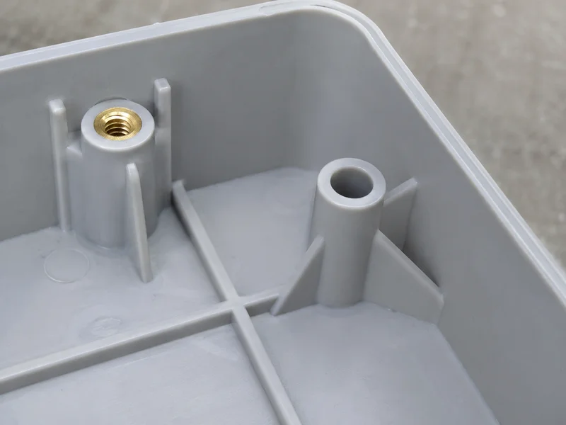
- Nominal wall: about 1.5–3 mm for small and medium housings
- Ribs: 50–60% of the wall, height up to about 3 times the wall
- Transitions: gradual, at least 3 times the wall length
- Inside corners: radius at least half the wall
- Large flat faces: add ribs or a slight curve to stay flat
For example, a 200 mm long flat cover in PC/ABS stays flatter with a shallow rib grid than with a thicker wall. Our guides to injection molding wall thickness and warpage plastic give more detail.
Key Takeaway: In other words, add stiffness with ribs and shape, not with thicker walls.
How Should Bosses and Fasteners Be Designed?
Bosses and fasteners should be designed to hold screws without sink or cracking.
| Fastener | Design rule |
|---|---|
| Self-tapping screw | Boss OD about 2–2.5 × screw diameter, hole per screw maker data |
| Heat-set or ultrasonic insert | Hole sized to insert data, boss wall about 1.5 mm or more |
| Molded-in insert | Insert supported in the mold, knurled for pull-out |
| Boss support | Gussets to the side wall, cored base |
For example, a boss joined to the side wall with two gussets resists screw torque better than a free-standing boss. Our guides to screw boss design and plastic threaded inserts explain the details.
Key Takeaway: For this reason, use inserts where a housing will be opened many times.
How Are Housing Halves Joined?
Housing halves are joined by snaps, screws, welding or adhesive, depending on service needs.
- Snap fits: fast, no extra parts, may need tool access to open
- Screws into bosses: strong, serviceable
- Brass inserts: many open and close cycles
- Ultrasonic welding: permanent, sealed, no fasteners
- Adhesive: for dissimilar materials or sealing
For example, a sealed sensor housing may be ultrasonically welded, while a meter housing that needs battery changes uses screws and inserts. Our guides to snap fit design and ultrasonic welding plastic compare these joints.
Key Takeaway: Overall, decide early whether the housing must be opened again.
Where Should Parting Lines, Gates and Ejectors Go on a Plastic Housing?
Parting lines, gates and ejectors on a plastic housing should sit away from cosmetic surfaces.
| Feature | Good location |
|---|---|
| Parting line | On an edge, step or lip between halves |
| Gate | Inside face, edge or under a label area |
| Ejector pins | Inside walls, ribs and bosses |
| Texture | Visible faces, with extra draft |
| Weld lines | Away from visible faces and loaded clips |
For example, a sub gate on an inner rib leaves no mark on the outer face of a handheld housing. Our guides to parting line injection molding, gate vestige and mold texture cover these choices.
Key Takeaway: Equally, mark A, B and C surfaces on the drawing before DFM.
How Can a Plastic Housing Be Sealed?
A plastic housing can be sealed with gaskets, overmolded seals or welding.
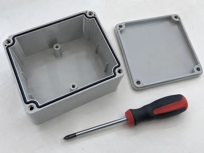
- Gasket in a groove: groove depth set for about 20–30% compression
- Overmolded TPE seal: seal molded onto one half
- Ultrasonic weld: permanent seal around the joint
- Flat, stiff sealing faces: ribs behind the seal line
- Screw spacing: close enough to compress the gasket evenly
For example, an outdoor control box may use a foamed gasket in a groove and stainless screws every 60–80 mm. Protection ratings follow IEC 60529, and our overmolding page explains molded-on seals.
Key Takeaway: As a rule, design flatness and compression first, then test the sealed assembly.
How Do You Prepare a Plastic Housing for Molding?
You prepare a plastic housing for molding by sending clear data and reviewing DFM.
- 3D models of all housing parts and mating parts
- 2D drawings with CTQs, A/B/C surfaces and texture
- Material grade and color standard
- Assembly method and sealing requirement
- Annual volume and target cost
- DFM review before mold design
For example, sending the PCB model with the housing lets the mold maker check boss positions and clearances. Our Engineering & DFM page describes the review.
Key Takeaway: Finally, review the housing with its contents, not as an empty shell.
FAQ
- Q: What is a plastic housing?
- A molded shell that encloses and protects electronics or mechanisms.
- Q: What wall thickness should a plastic housing have?
- Usually about 1.5–3 mm, kept as uniform as possible.
- Q: Which plastic is best for housings?
- ABS or PC/ABS for most devices; PC for impact; PA GF for strength.
- Q: How are housing halves joined?
- With snap fits, screws and inserts, ultrasonic welding or adhesive.
- Q: How do I avoid sink marks on a housing?
- Keep bosses and ribs thinner than the wall and core out thick areas.
Conclusion
A good plastic housing is designed around even walls, strong bosses, clean cosmetic faces and the right joining method. Review it with its contents before tooling. To check your housing design, send your 3D model and 2D drawing to our engineers.