
Overmolding Design Guide: Materials, Retention and Walls
This overmolding design guide explains how to mold a second material, usually a soft TPE or TPU, over a rigid substrate so the two act as one part. Overmolding adds soft-touch grips, seals, bumpers, vibration damping and multi-color appearance to handles, tools, housings, wearable parts and connectors. The design challenge is making the overmold stay attached: chemical bonding alone is not always enough, so mechanical retention, material pairing and process control all matter.
Most overmold failures are peeling and delamination at edges. For example, a TPE grip with a thin, feathered edge may lift after a few weeks of use, while the same grip ending in a groove with interlocks stays put. In this guide, we explain overmolding design: material compatibility, mechanical retention, wall thickness and edges, substrate tolerance and preheating, delamination causes, peel adhesion testing and tooling choices. For mold types, see our guide to overmold tooling.
An overmolding design guide starts with a compatible material pair (for example TPE grades formulated to bond to PC, ABS or PA), then adds mechanical retention such as through-holes, undercuts, grooves and interlocks for joints that must survive peel and shear. Keep overmold walls about 1–3 mm, end edges in grooves or against shoulders rather than feathered, control substrate tolerance and cleanliness, preheat the substrate when bonding needs it, and verify adhesion with peel tests. Choose two-shot or insert-style overmolding by volume and part size.
In short: pair compatible materials, add mechanical retention, protect edges and test peel strength.
Key points:
- Bond: compatible material pairs are the base.
- Retention: mechanical features back up the bond.
- Edges: grooves and shoulders prevent peeling.
What Does an Overmolding Design Guide Cover?
An overmolding design guide covers the decisions that make a two-material part bond, fill and survive use.
Main decisions:
- Material pairing for chemical bonding
- Mechanical retention features
- Overmold thickness and edges
- Substrate design and tolerance
- Process: two-shot or insert overmolding
- Testing: peel, pull and aging
For example, a power tool handle uses a PA6-GF substrate with a TPE grip bonded and locked through holes. Our overmolding service molds such parts. For the process comparison, see two-shot molding vs overmolding.
Key Takeaway: Treat the overmold interface as a designed joint, not a coating.
Which Overmolding Materials Bond Well?
Overmolding materials bond well when the overmold grade is formulated for the substrate.
| Substrate (typical) | Common overmold materials |
|---|---|
| PP | TPE (SEBS-based), TPV |
| ABS, PC, PC/ABS | TPE grades for styrenics/PC, TPU |
| PA6, PA66 (incl. GF) | Modified TPE, TPU |
| PBT | TPU, specific TPE grades |
| Metal | Usually mechanical retention or primers |
For example, a standard PP-bonding TPE will not bond to PA66; a nylon-bonding grade is needed. Resin suppliers publish compatibility charts. Our guide to TPE injection molding process explains TPE grades.
Key Takeaway: Confirm the overmold grade is formulated for the exact substrate material.
How Do You Add Mechanical Retention When an Overmold Bond Is Not Enough?
You add mechanical retention when an overmold bond is not enough by designing features that physically lock the overmold to the substrate.
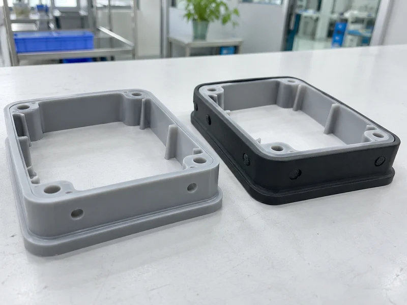
Retention features:
- Through-holes so the overmold flows through and locks on the back
- Undercuts and dovetail grooves
- Ribs and interlocks that resist shear
- Wrap-around edges that capture the substrate
- Textured substrate surfaces for extra grip
For example, a TPE bumper on a PC housing can flow through 2 mm holes and form rivet-like heads inside. Even if the chemical bond weakens, the bumper stays in place. Our guide to 8 ways to achieve undercut success explains undercut features.
Key Takeaway: Add mechanical locks wherever the overmold sees peel or shear in use.
What Wall Thickness and Edge Rules Does This Overmolding Design Guide Recommend?
This overmolding design guide recommends uniform overmold walls and protected edges.
Rules:
- Overmold thickness: about 1–3 mm, uniform
- Avoid feathered edges: end the overmold in a groove or against a shoulder
- Shut-off design: sharp, positive shut-offs on the substrate
- Substrate wall: thick enough not to deform under overmold pressure
- Flow length: short enough to fill thin TPE sections
For example, a grip that ends in a 0.5 mm deep groove resists peeling far better than one that tapers to nothing. Our guide to basics of injection molding design covers wall rules.
Key Takeaway: Never let an overmold end in a thin feather edge.
How Do Substrate Tolerance and Preheating Affect Overmolding?
Substrate tolerance and preheating affect overmolding because the substrate must fit the second cavity and accept the bond.
Substrate tolerance:
- Shut-off areas must fit tightly to prevent flash.
- Too large: the substrate is crushed or marked.
- Too small: overmold flashes past the shut-off.
- Warpage of the substrate affects fit.
Substrate preheating:
- Warmer substrates often bond better with TPE.
- Two-shot molding keeps the substrate warm naturally.
- Insert-style overmolding may need preheating of molded substrates.
- Moisture: dry hygroscopic substrates such as PA before overmolding.
For example, PA66 substrates stored for days may absorb moisture and bond poorly; drying them restores adhesion. Our guide to plastic resin drying explains moisture control.
Key Takeaway: Control substrate size, temperature and moisture as carefully as the overmold.
What Does an Overmolding Design Guide Say About Delamination?
Any overmolding design guide warns that delamination is caused by poor bonding, stress at edges or contamination.
Common causes:
- Incompatible material pair
- Contaminated substrate (oil, release agent, dust)
- Cold or damp substrate
- Low overmold melt temperature
- Feathered edges and sharp corners
- High shrinkage stress in thick overmold areas
For example, mold release spray on a substrate tool can transfer to parts and stop bonding. Removing it often solves the problem. Our guide to injection molding defects and solutions covers related defects.
Key Takeaway: Check cleanliness and material pairing first when overmolds peel.
How Is TPE Overmold Peel Adhesion Tested?
TPE overmold peel adhesion is tested by peeling the overmold from the substrate and measuring force or failure mode.
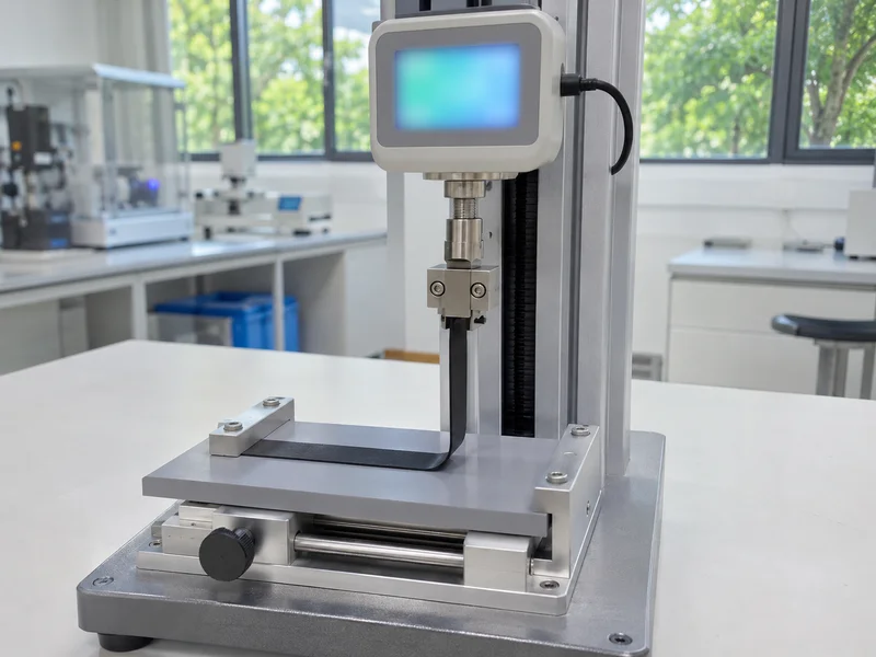
Test practice:
- Peel test: pull a strip at 90° or 180° and record force
- Failure mode: cohesive failure (TPE tears) is better than adhesive failure (clean separation)
- Aging: heat, humidity or chemical exposure before testing
- Production checks: simple manual peel checks per lot
For example, a grip may require cohesive failure on every sample after 72 hours at 70 °C. Peel test methods are described by ASTM International, such as ASTM D903 for adhesives, adapted for overmolds.
Key Takeaway: Specify the failure mode, not only the force.
FAQ
- Q: What is overmolding?
- Molding a second material, often TPE, over a rigid substrate to form one part.
- Q: Which materials can be overmolded together?
- Compatible pairs such as TPE on PP, PC or ABS, and specific grades on PA.
- Q: Why does an overmold peel off?
- Incompatible materials, contamination, cold substrates or feathered edges.
- Q: How thick should an overmold be?
- Typically about 1–3 mm, kept uniform.
- Q: How is overmold adhesion tested?
- With peel tests, checking both force and failure mode.
Conclusion
This overmolding design guide comes down to compatible materials, mechanical retention, protected edges, controlled substrates and peel testing. Design the interface as a joint. To review an overmolded part, send your 3D model and 2D drawing to our engineers.