
CNC Machining for Assemblies: Datums and Tolerance Stacks
CNC machining for assemblies means machining parts that must fit together, such as a housing with a cover, a bracket with bearing blocks, a manifold with valve bodies or a fixture with locating plates. Each part may meet its own drawing and the assembly can still fail: holes do not line up, bearings bind, covers rock or seals leak. Precision assemblies need the parts to be designed, toleranced, machined and inspected as a system.
The most reliable assemblies are planned around how parts locate on each other. For example, a sensor mount located by two dowel pins repeats its position within microns every time it is reassembled, while the same mount located only by four clearance-hole screws can shift by a tenth of a millimeter. In this guide, we explain CNC machining for assemblies: assembly-driven datums, locating methods, tolerance allocation, machining matched features, assembly and verification, and how to brief a supplier. For tolerance analysis, see our guide on how to do a tolerance stack up analysis.
CNC machining for assemblies works when each part’s datums match how it locates in the assembly, critical interfaces use precise locating features such as dowel pins and machined shoulders, tolerances are allocated with a stack-up analysis, related features are machined in one setup, and parts are verified both individually and as an assembled set. Fasteners in clearance holes should clamp, not locate. Suppliers need the assembly model or drawing, the critical fits, and any requirement to machine, mark or ship parts as matched sets.
In short: design datums around the assembly, locate with pins and shoulders, allocate tolerances and verify the assembled result.
Key points:
- Datums: match the assembly interfaces.
- Locating: dowels and shoulders locate; screws clamp.
- Verification: check parts and the assembled set.
What Is CNC Machining for Assemblies?
CNC machining for assemblies is machining multiple parts so they fit and function together, not only individually.
Typical assemblies:
- Housings and covers with seals
- Brackets and bearing blocks
- Manifolds with valve bodies
- Fixtures with locating plates
- Sensor and camera mounts
For example, a camera mount assembly may include a base plate, an angle bracket and a clamp ring, each machined separately but required to align an optical axis. Our CNC machining services machine small and medium precision parts that are often supplied as matched sets.
Key Takeaway: Above all, assembly function defines the critical features of each part.
How Should Datums Be Chosen for CNC Machining for Assemblies?
Datums for CNC machining for assemblies should be chosen from the features that contact or locate mating parts.
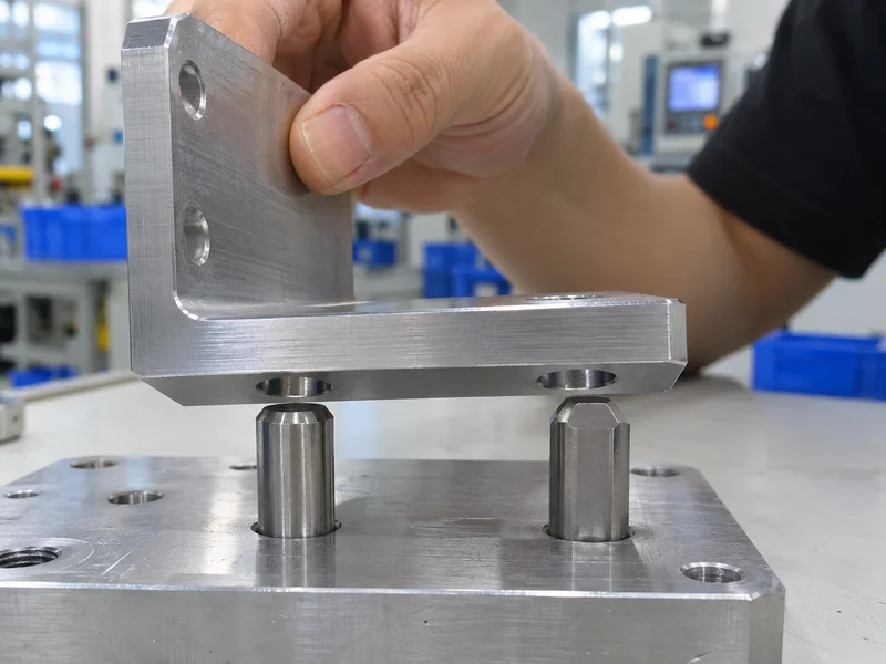
Guidelines:
- Primary datum: the main mounting face
- Secondary and tertiary: dowel holes, slots or shoulders that locate
- Same datums on mating parts’ drawings
- Machine datums first in the process
For example, a bracket that mounts on a base with two dowels should use its bottom face and those two dowel holes as A, B and C, with the base using matching features. Our guide to GD&T position tolerance explains datum frames.
Key Takeaway: In other words, matching datums across parts is the foundation of a good assembly.
Which Locating Methods Work Best in Machined Assemblies?
Locating methods that work best in machined assemblies are precise, repeatable features that do not rely on screws.
| Method | Repeatability | Notes |
|---|---|---|
| Two dowel pins (round + diamond) | Very high | Common for precision plates |
| Pin and slot | High | Allows thermal expansion |
| Machined shoulders and spigots | High | Good for round parts |
| Tapered pins | Very high | For frequent disassembly |
| Screws in clearance holes | Low | Clamp only, do not locate |
For example, using one round pin and one diamond pin prevents over-constraint while keeping repeatable location. Our guide to tolerance for slip fit explains pin fits.
Key Takeaway: For this reason, let pins and shoulders locate and screws only clamp.
How Should Tolerances Be Allocated Across Parts?
Tolerances should be allocated across parts using a stack-up analysis of each critical assembly requirement.
Steps:
- Define the assembly requirement, such as alignment within 0.05 mm.
- Identify contributing features on each part.
- Run a stack-up, worst case or statistical.
- Tighten the biggest contributors only.
- Use GD&T to control position and orientation efficiently.
For example, if two parts each contribute ±0.05 mm to a 0.1 mm alignment requirement, tightening the dowel hole positions on one part may solve it without tightening everything. Statistical tolerancing concepts are described in standards from ISO.
Key Takeaway: Overall, allocate tolerance where it costs least to hold.
How Should Matched Features Be Machined?
Matched features should be machined so their relationship is controlled by one setup or by matched machining.
Methods:
- Machine related features in one setup
- Line-bore bearing bores across assembled parts when needed
- Match-drill or ream dowel holes in assembled parts for critical alignment
- Mark matched sets so they stay together
- Use multi-axis machining to reach several faces in one setup
For example, two housing halves may be bolted together and line-bored so bearing bores align, then marked as a set. Our guide to multi axis CNC machining explains one-setup machining.
Key Takeaway: Equally, matched machining gives the best alignment but requires sets to stay together.
How Should CNC Machining for Assemblies Be Verified?
CNC machining for assemblies should be verified both part by part and as assembled sets.
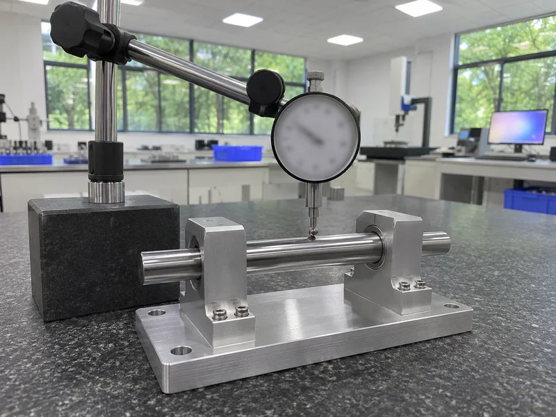
Verification:
- Part inspection of critical features
- Trial assembly of first articles
- Functional checks: rotation, sealing, alignment
- Assembled measurement of critical outputs
- Records linking part lots and sets
For example, a bearing block assembly may be checked for free rotation and shaft alignment after assembly, in addition to bore measurements. Our quality control and inspection process records such checks when specified. Our guide to the first article inspection report explains FAI.
Key Takeaway: As a rule, a trial assembly of first articles catches problems drawings miss.
How Should You Brief a Supplier on Assembly Parts?
You should brief a supplier on assembly parts with enough information to understand how they fit together.
Briefing items:
- Assembly model or drawing, even if parts are quoted separately
- Critical interfaces and fits marked
- Matched-set requirements
- Assembly or trial-fit requirements
- Packaging that keeps sets together and protects surfaces
- Inspection documents required
For example, telling the supplier that two plates must align within 0.02 mm lets them plan matched dowel machining. Our engineering and DFM review uses the assembly context to suggest locating features.
Key Takeaway: Finally, share the assembly, not just individual part drawings.
FAQ
- Q: What is CNC machining for assemblies?
- Machining parts that must fit and function together, with datums and tolerances planned for the assembly.
- Q: Why use dowel pins in machined assemblies?
- They locate parts repeatably; screws in clearance holes only clamp.
- Q: How are tolerances allocated in an assembly?
- With a tolerance stack-up of each critical requirement.
- Q: What is line boring?
- Boring aligned holes across assembled parts in one operation.
- Q: Should suppliers see the assembly drawing?
- Yes. It shows critical interfaces and helps plan machining and inspection.
Conclusion
CNC machining for assemblies succeeds when datums match assembly interfaces, pins and shoulders locate, tolerances are allocated by stack-up and assemblies are verified as sets. Share the assembly context with your supplier. To review an assembly, send your 3D model and 2D drawing to our engineers.