
Injection Mold Design Software: How to Pick the Best One
Injection mold design software is the set of CAD, simulation and CAM tools a mold maker uses to turn a part model into a buildable mold. CAD systems such as Siemens NX, CATIA, Creo and SolidWorks model the mold; simulation tools such as Autodesk Moldflow and Moldex3D predict filling, cooling and warpage; and CAM software creates the CNC and EDM programs that cut the steel.
Buyers do not need the same software as their mold maker. For example, a customer who designs in SolidWorks can send a STEP file and a PDF drawing, and a mold shop working in NX will build the mold design from that data without any loss that matters for the mold. In this guide, we explain what injection mold design software does, the main CAD systems, simulation tools, CAM and EDM software, file formats, what customers need, and how software is used in our projects. For design principles, see our guide to injection molding tool design.
Injection mold design software covers three stages. CAD tools (Siemens NX with Mold Wizard, CATIA, Creo with EMX, SolidWorks with mold plug-ins, Cimatron, ZW3D) split cores and cavities and design the mold base, cooling, ejection and slides. CAE tools (Autodesk Moldflow, Moldex3D, SolidWorks Plastics, Cadmould) simulate filling, packing, cooling and warpage. CAM tools (NX CAM, hyperMILL, PowerMill, Mastercam) program machining and electrodes. Neutral formats such as STEP and Parasolid move data between systems.
In short: CAD designs the mold, CAE checks it, CAM builds it.
Key points:
- CAD: mold structure and parting.
- CAE: flow, cooling and warpage prediction.
- CAM: CNC and EDM programs.
What Does Injection Mold Design Software Do?
Injection mold design software helps mold designers complete each step of the mold design.
- Part check: draft, undercuts and wall thickness analysis
- Parting: parting line, shutoffs, core and cavity split
- Layout: cavity count, runner and gates
- Mold base: standard bases from HASCO, Meusburger, DME and LKM libraries
- Systems: cooling, ejection, slides and lifters
- Drawings: 2D drawings and bills of materials
For example, a draft analysis in the CAD system flags a 0° wall before the parting line is set. Our guide to draft angle guidelines explains the rules being checked.
Key Takeaway: Above all, mold software speeds design, but engineering judgment still sets the mold concept.
Which CAD Systems Do Mold Makers Use?
Mold makers use CAD systems with dedicated mold design modules.
| CAD system | Mold tools | Typical users |
|---|---|---|
| Siemens NX | Mold Wizard, electrode design | Precision and automotive mold shops |
| CATIA | Mold tooling design | Automotive and aerospace programs |
| PTC Creo | EMX mold base extension | Product companies, some mold shops |
| SolidWorks | Mold tools plus plug-ins | Product design, small tool shops |
| Cimatron | Integrated mold design and CAM | Mold shops |
| ZW3D | Mold design and CAM | Cost-focused mold shops |
For example, NX is widely used in Asian and European mold shops because design, electrodes and CAM work in one system. Our guide to mold base explains the standard libraries.
Key Takeaway: In other words, the best CAD is the one the mold team uses well every day.
Which Simulation Tools Check the Design?
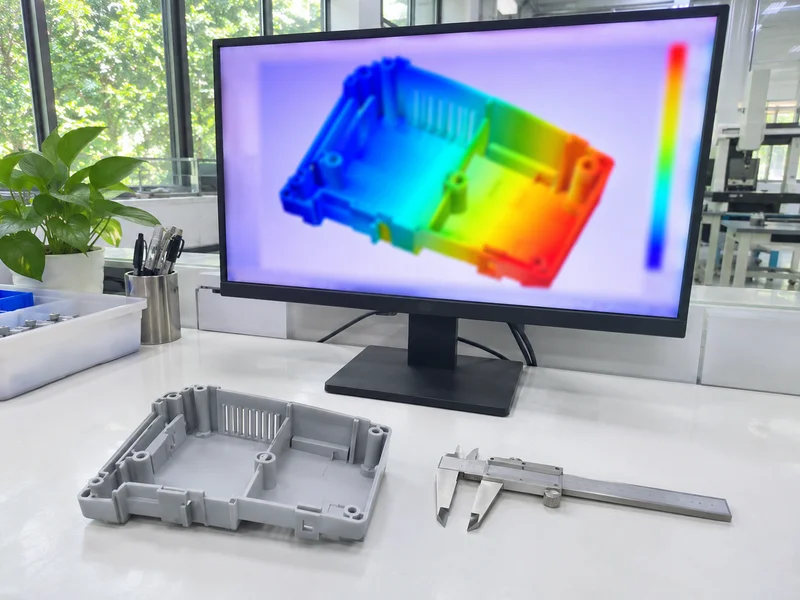
Simulation tools check how the mold will fill, cool and warp before steel is cut.
| Tool | Main use |
|---|---|
| Autodesk Moldflow | Fill, pack, cool, warp, fiber orientation |
| Moldex3D | 3D flow, cooling and warpage |
| SolidWorks Plastics | Early fill checks inside CAD |
| Cadmould | Fill and warpage analysis |
For example, a fill study can show a weld line on a cosmetic face, so the gate is moved before the design is released. Our guide to mold flow analysis explains the results.
Key Takeaway: For this reason, run simulation when the risk justifies it, not as a formality.
Which CAM and EDM Software Turns Design Into Steel?
CAM and EDM software turns the approved design into machining programs.
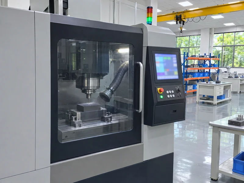
- CNC programming: NX CAM, hyperMILL, PowerMill, Mastercam
- 5-axis milling: deep cavities and complex cores
- Electrode design: extracting electrode shapes for sinker EDM
- Wire EDM programming: profiles, inserts and slide pockets
- CMM programs: checking critical features
For example, electrodes for deep ribs are extracted from the core model and programmed for graphite milling. Our guides to sinker EDM and wire EDM explain the processes.
Key Takeaway: Overall, linked CAD and CAM reduce errors between design and steel.
How Do File Formats Affect Injection Mold Design Software?
File formats affect injection mold design software because each system reads native files differently.
| Format | Use | Note |
|---|---|---|
| STEP (.stp) | Most common neutral 3D format | Defined in ISO 10303 |
| Parasolid (.x_t) | Clean exchange to NX and SolidWorks | Very reliable |
| IGES (.igs) | Older surface exchange | May lose faces |
| Native files | Same software only | Version issues |
| PDF / DWG | 2D drawings with tolerances | Always needed |
For example, a STEP AP214 file plus a PDF drawing gives the mold designer both geometry and tolerances. The STEP standard is published by ISO. Our injection molding quote RFQ checklist lists files to send.
Key Takeaway: Equally, send a neutral 3D file and a 2D drawing together.
What Software Do Customers Need?
Customers need no mold software to buy a mold.
- Send: STEP or Parasolid model plus PDF drawing
- Review: DFM reports in PDF
- View 3D: free viewers for STEP files
- Approve: mold design screenshots and section views
For example, a buyer can approve a mold layout from a PDF that shows the parting line, gates, ejector pins and cooling in color. Our Engineering & DFM page shows what a DFM review covers.
Key Takeaway: As a rule, focus on clear data and reviews, not on matching software.
How Do We Use Injection Mold Design Software?
We use injection mold design software across design, simulation and machining.
- Siemens NX CAD/CAM on six seats for mold design and programming
- Moldflow Advanced applied according to project complexity and customer requirements
- 5-axis and 3-axis CNC, sinker and wire EDM fed from the same models
- CMM checking of critical features against the design
For example, a small precision connector mold is designed in NX, checked in Moldflow for filling balance and programmed for electrode and insert machining from the same model. Our injection mold manufacturing page explains the full process.
Key Takeaway: Finally, ask a mold maker how its software links design to machining and inspection.
FAQ
- Q: What software is used for injection mold design?
- Siemens NX, CATIA, Creo, SolidWorks, Cimatron and ZW3D for CAD, with Moldflow or Moldex3D for simulation.
- Q: Is SolidWorks good for mold design?
- It works for simple molds and with plug-ins; many mold shops use NX for complex tools.
- Q: Do I need Moldflow for every mold?
- No, it is most useful for complex, cosmetic or warpage-sensitive parts.
- Q: Which file format should I send?
- STEP or Parasolid for 3D, plus a PDF drawing.
- Q: Can a mold maker use my native CAD file?
- Often yes, but a neutral file avoids version problems.
Conclusion
Injection mold design software links CAD design, simulation and CAM so a mold can be designed, checked and built from one model. Customers only need to supply clean 3D and 2D data. To start a mold design review, send your 3D model and 2D drawing to our engineers.