
Flow Marks in Injection Molding: How to Get Best Results
Flow marks in injection molding are wavy lines, ripples or rings on the surface of a molded part that show how the melt front moved through the cavity. They are cosmetic defects, but on visible parts, especially glossy or dark ones, they are a common reason for rejection. Because they record the history of filling and cooling, flow marks can also point directly to where the process or tool needs to change.
The same word “flow marks” is often used for several different defects. For example, concentric ripples near the end of fill usually mean a hesitating, cooling flow front, while a dull band right at the gate is gate blush. In this guide, we explain flow marks in injection molding: the main types, their causes, how to read them to locate a flow-front or cooling issue, and the process, tool and design fixes. For a wider map of defects, see our guide to injection molding defects and solutions.
Flow marks in injection molding are surface patterns such as ripples, waves, tiger stripes or rings that form when the melt front cools, slows or advances unevenly against the mold surface. Common causes are low melt or mold temperature, slow or inconsistent injection speed, hesitation at thin sections, wall thickness changes, small gates and insufficient packing. Fixes include raising mold and melt temperature, increasing or profiling injection speed, adjusting gate size and location, smoothing wall transitions and improving venting. Reading where the marks start shows whether the issue is the flow front or cooling.
In short: flow marks show where the melt front slowed or cooled; keep it hot and moving steadily.
Key points:
- Types: ripples, tiger stripes, rings and hesitation marks.
- Location: tells you where the flow front struggled.
- Fixes: temperature, speed, gate and wall design.
What Are Flow Marks in Injection Molding?
Flow marks in injection molding are visible patterns that follow the path of the melt across the part surface.
Common types:
- Ripples or waves: fine ridges perpendicular to flow, often near the end of fill
- Tiger stripes: alternating glossy and dull bands, common in filled PP and PC/ABS
- Hesitation rings: marks where flow paused at a thin section
- Halo or ring patterns around holes or bosses
For example, a black PP cover may show tiger stripes along its length, while a thin PC window may show ripples near the far edge. Our guide to 8 common injection molding defects gives an overview.
Key Takeaway: Name the pattern first. Each type has a typical cause.
What Causes Flow Marks in Injection Molding?
Flow marks in injection molding are caused by the melt front freezing, slipping or slowing unevenly against the mold wall.
Main causes:
- Low mold temperature: skin freezes too quickly
- Low melt temperature: higher viscosity and slow flow
- Slow or uneven injection speed
- Hesitation at thin sections or around obstacles
- Wall thickness changes that alter flow speed
- Small or poorly placed gates
- Insufficient packing that fails to press the skin against the mold
For example, ripples that disappear when mold temperature rises by 15 °C were caused by early skin freezing. Our guide to practical mold cooling explains mold temperature control.
Key Takeaway: Most flow marks point to a cold or slow flow front.
How Do You Read Flow Marks to Locate the Issue?
You read flow marks by noting where they start, which direction they run and how they change with process settings.
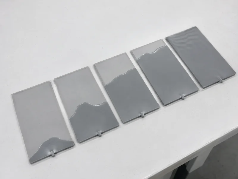
Reading guide:
| Where the marks appear | Likely issue |
|---|---|
| Near the gate | Gate design, initial speed (possibly gate blush) |
| At the end of fill | Melt cooling, low speed, poor venting |
| After a thin section | Hesitation |
| Around holes or bosses | Flow splitting and rejoining |
| Alternating bands along flow | Unstable flow front (tiger stripes) |
For example, marks appearing just after a thin rib suggest the flow hesitated there, so thickening the rib or reordering filling helps. Short-shot studies show the flow front step by step. Our guide to gate blush injection molding covers marks right at the gate.
Key Takeaway: Run short shots to watch the flow front reach the problem area.
How Do Process Changes Fix Flow Marks in Injection Molding?
Process changes fix flow marks in injection molding by keeping the melt front hot and moving steadily.
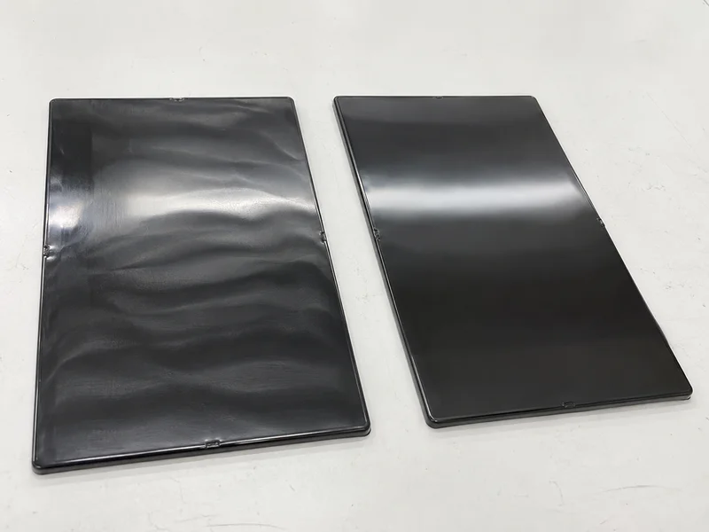
Process fixes:
- Raise mold temperature to slow skin freezing.
- Raise melt temperature within the supplier’s range.
- Increase injection speed or profile it to avoid hesitation.
- Increase pack pressure and time to press the skin.
- Check nozzle and hot runner temperatures.
- Dry the material to avoid moisture-related marks.
For example, tiger stripes on a talc-filled PP part can be reduced by faster injection and higher mold temperature. Our guide to scientific molding explains speed and pressure studies.
Key Takeaway: Try mold temperature and injection speed first. They solve most flow marks.
How Do Tool and Design Changes Prevent Flow Marks?
Tool and design changes prevent flow marks when process changes cannot.
Tool and design fixes:
- Enlarge the gate or change its type
- Move the gate to give a more even flow path
- Smooth wall thickness transitions
- Avoid thin sections before thick areas
- Improve venting at the end of fill
- Add texture to hide minor marks
- Use rapid heat cycle molding for high-gloss parts, where justified
For example, a part that fills from thin to thick often shows hesitation marks; gating into the thick section reverses this. Our guide to injection mold venting explains vent design.
Key Takeaway: Gate into thick sections and avoid sudden thickness changes.
Which Materials Show Flow Marks Most?
Some materials show flow marks more because of their viscosity, fillers or surface gloss.
- Talc- or glass-filled PP: tiger stripes
- PC and PC/ABS: ripples and gloss differences
- PMMA: visible flow lines in clear parts
- ABS in dark glossy colors: shows any surface variation
- Metallic-effect pigments: show flow direction strongly
For example, a metallic-effect ABS part shows flow lines that may be impossible to remove completely; a solid color or texture may be a better choice. Our guide to ABS injection molding covers ABS appearance.
Key Takeaway: Agree color, gloss and texture early for flow-mark-sensitive materials.
How Should Flow Marks Be Specified in Cosmetic Requirements?
Flow marks should be specified in cosmetic requirements by surface class, viewing conditions and boundary samples.
Specification items:
- Surface classes (A, B, C)
- Viewing distance and lighting
- Acceptable mark size and visibility
- Boundary samples approved at trial
- Texture or gloss standard
For example, “no visible flow marks on A surfaces at 500 mm under diffuse light” is testable. Our plastic injection molding service uses approved samples for cosmetic parts. Standard practice for visual appearance evaluation is described by ASTM International.
Key Takeaway: Approve boundary samples before production.
FAQ
- Q: What are flow marks in injection molding?
- Ripples, waves or bands on the part surface that show uneven melt front movement.
- Q: What causes flow marks?
- Low mold or melt temperature, slow injection, hesitation, wall changes and small gates.
- Q: How do you fix flow marks?
- Raise mold and melt temperature, increase injection speed, and improve gates and wall transitions.
- Q: What are tiger stripes in injection molding?
- Alternating glossy and dull bands caused by an unstable flow front, common in filled PP.
- Q: Are flow marks a structural defect?
- Usually not, but they can be linked to weld lines or weak areas.
Conclusion
Flow marks in injection molding record where the melt front slowed or cooled. Read their location, then fix with temperature, speed, gate and wall changes, and agree cosmetic criteria with samples. To review a cosmetic part, send your 3D model and 2D drawing to our engineers.