
Ejector Pins: Types, Materials, Fits and Placement
Ejector pins are hardened steel pins that push a molded part off the core when an injection mold opens. They sit in the moving half of the mold, are driven by the ejector plate and return before the next shot. Their size, number, position and fit decide whether parts release cleanly or stick, distort, flash or show marks.
Most ejection problems come from too few pins or pins in the wrong place. For example, a thin-walled box ejected by four small pins at the corners may crack or whiten, while the same box with pins under its ribs and a stripper edge ejects cleanly. In this guide, we explain ejector pins: types, materials, sizes and fits, placement rules, alternatives, common problems and how to specify and replace them. For the marks they leave, see our guide to ejector pin marks.
Ejector pins are standard mold components, usually made of nitrided hot-work steel (1.2344 / H13) or through-hardened tool steel, supplied to standards such as ISO 8694 or DIN 1530 in diameters from about 1 mm to 25 mm. They are mounted in the ejector retainer plate and fitted into the core with a small clearance that lets air vent but stops plastic flashing. Designers place them on ribs, bosses, walls and flat areas, balance the ejection force, and use stepped pins, blade ejectors, sleeves or stripper plates where round pins are not enough.
In short: enough pins, in strong areas, with the right fit, give clean ejection.
Key points:
- Function: push the part off the core.
- Standards: ISO 8694 and DIN 1530 pins.
- Design: placement, number and fit.
What Are Ejector Pins?
Ejector pins are cylindrical pins that transfer force from the ejector plate to the molded part.
How the system works:
- Ejector plates carry the pins and move forward at mold opening
- Pins push on the part face or features
- Return pins and springs bring the plates back
- Guided ejection keeps plates aligned on larger molds
For example, in a small two-cavity mold, eight pins per cavity may push each part off its core in a stroke of 15 mm. Our guide to injection mold components shows where the ejector system sits.
Key Takeaway: Above all, ejector pins are part of a system; plates, guides and return pins matter too.
What Types of Ejector Pins Are Used?
Several types of ejector pins are used depending on feature size and shape.
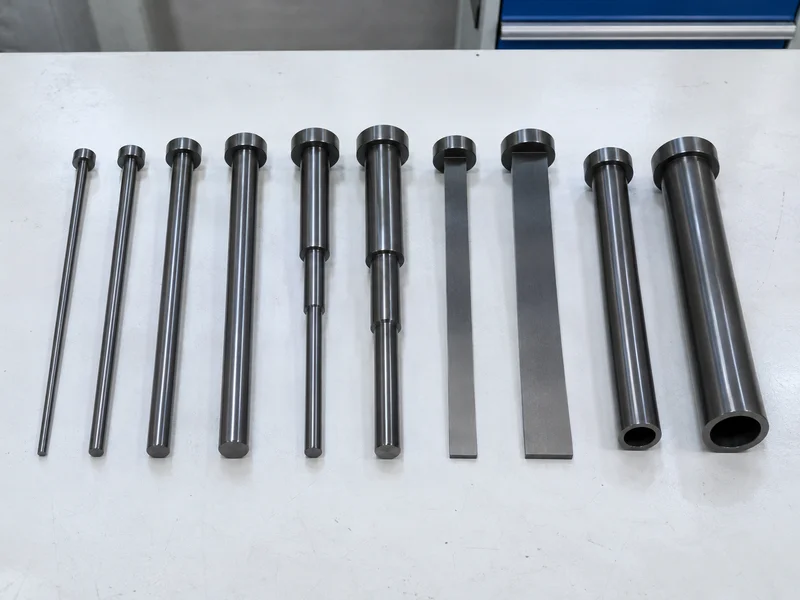
| Type | Use |
|---|---|
| Straight ejector pin | General ejection on flat areas and ribs |
| Stepped pin | Small diameters with a stronger shank |
| Blade (flat) ejector | Thin ribs and narrow walls |
| Ejector sleeve | Around core pins in bosses |
| Contoured pin with anti-rotation | Sloped or shaped surfaces |
| Stripper plate or ring | Round, thin-walled parts |
For example, a boss with a core pin is ejected by an ejector sleeve around the pin instead of a separate pin beside it. Our guide to ejector sleeves explains sleeve design.
Key Takeaway: In other words, choose the ejector shape to match the feature being pushed.
Which Materials and Hardness Are Common?
Common materials are nitrided hot-work steel and through-hardened tool steel.
- 1.2344 / H13 nitrided: hard surface, tougher core, good for hot molds
- 1.2210 or similar through-hardened: about 60 HRC, for general use
- High-speed steel: small diameters needing stiffness
- DLC or other coatings: reduce galling and sticking
For example, pins in a mold running PA66 GF at high mold temperature are often nitrided H13 to resist wear and galling. Our guide to heat treatment of steel explains nitriding and hardening.
Key Takeaway: For this reason, select pin material for the mold temperature and resin abrasiveness.
How Are Pin Sizes and Fits Chosen?
Ejector pin sizes and fits are chosen to carry the ejection force without bending and without flash.
Guidelines:
- Diameter as large as the feature allows
- Stepped pins when the working diameter is under about 3 mm
- Fit length of a few diameters in the core, with relief behind it
- Clearance smaller than the resin’s flash limit
- Length set so the pin face is flush with the part surface
| Resin flow behavior | Typical clearance approach |
|---|---|
| Low viscosity (PA, PBT, LCP) | Very tight fit to prevent flash |
| Medium (ABS, PC, POM) | Standard tight fit |
| Higher viscosity (PC/ABS, filled grades) | Slightly larger fit tolerated |
For example, a 1.5 mm pin in a long core is made as a stepped pin with a 4 mm shank so it does not buckle. Our guide to injection molding flash explains flash limits.
Key Takeaway: Overall, use the largest diameter and the shortest unsupported length possible.
Where Should They Be Placed on the Part?
Ejector pins should be placed where the part is strong and where it grips the core.
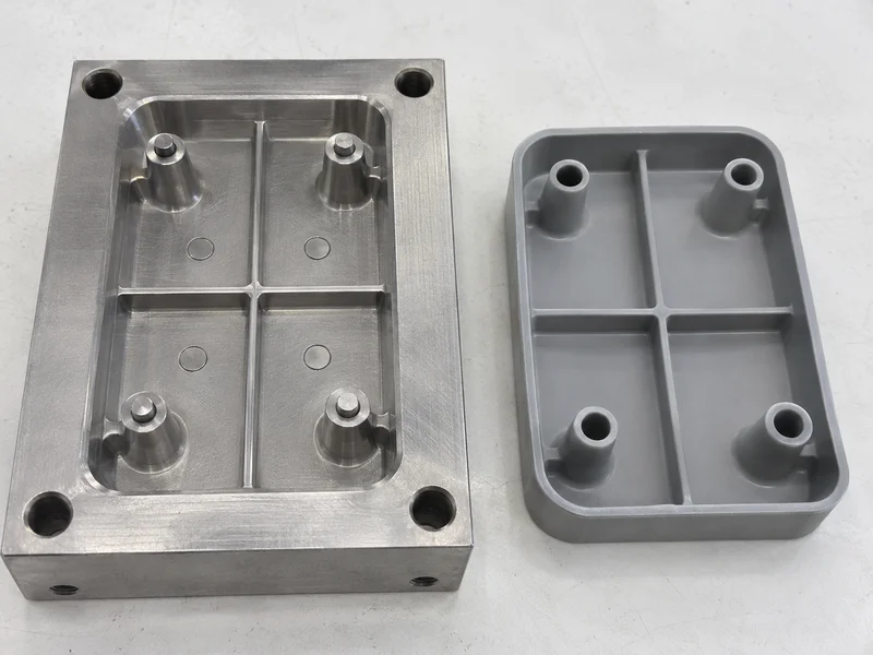
Placement rules:
- Under ribs and bosses, which grip the core most
- Near deep walls and corners
- On flat areas, not on sloped faces without anti-rotation
- Away from cosmetic surfaces, or with agreed mark positions
- Balanced around the part so it pushes off evenly
- Clear of cooling channels and slides
For example, a cover with a glossy top face is ejected from its inside ribs, so marks stay hidden. Our guide to injection molding wall thickness explains how ribs affect release.
Key Takeaway: Equally, mark ejector positions on the part drawing before the mold design is released.
What Problems Do Ejector Pins Cause?
Ejector pins cause problems when force, fit or placement is wrong.
| Problem | Likely cause | Fix |
|---|---|---|
| Stress whitening or cracks | Too few pins, too small area | More or larger pins, sleeves or stripper |
| Deep pin marks | Part too hot, pins too long | More cooling time, adjust pin length |
| Flash around pins | Worn or loose fit | Replace pins, re-bush holes |
| Bent or broken pins | Unsupported length, misalignment | Stepped pins, guided ejection |
| Galling or seizing | Poor lubrication, heat | Coated pins, correct lubricant |
For example, flash rings around older pins usually mean the holes have worn and the pins need replacing. Our guide to maintenance of molds covers inspection.
Key Takeaway: As a rule, flash around pins is a wear signal, not a process problem.
How Should Ejector Pins Be Specified and Replaced?
Ejector pins should be specified by standard, size, material and quantity, and spares should be kept.
Specification items:
- Standard, such as ISO 8694 or DIN 1530 (see ISO)
- Diameter, length and head type
- Material and treatment, such as nitrided 1.2344
- Anti-rotation for contoured pins
- Spare quantity for wear parts
For example, a mold specification may state “Ejector pins ISO 8694, nitrided 1.2344, standard brand per customer, 10% spares”. We supply paid spare parts such as ejector pins and sleeves on request with export molds. Our injection mold manufacturing team designs ejection systems for small and medium precision molds.
Key Takeaway: Finally, keep spare pins for every size in the mold to avoid long stops.
FAQ
- Q: What do ejector pins do?
- They push the molded part off the core when the mold opens.
- Q: What are ejector pins made of?
- Usually nitrided hot-work steel such as 1.2344 / H13, or through-hardened tool steel.
- Q: Why are there circles on plastic parts?
- They are ejector pin marks where the pins pushed the part.
- Q: How do you stop flash around ejector pins?
- Keep the pin fit within the resin’s flash limit and replace worn pins.
- Q: What standard covers ejector pins?
- Common standards include ISO 8694 and DIN 1530.
Conclusion
Ejector pins decide whether parts release cleanly. Choose the right type and material, use the largest practical diameter, place pins under ribs and strong areas, keep fits tight and keep spares. To review the ejection of your part, send your 3D model and 2D drawing to our engineers.